WEEK 1 - NUKE 3D &
CAMERA PROJECTION
3D WORKSPACE & CAM PROJECTION


-
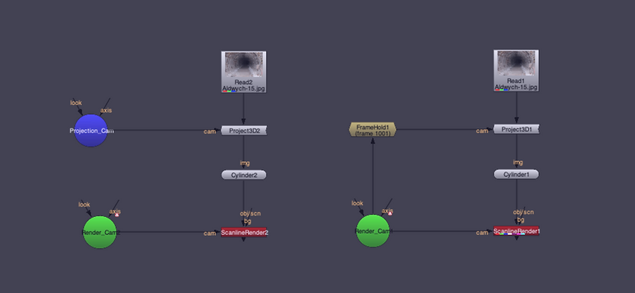
The Scene node groups together lights and geometry in order to pass them on to a render node.
-
When connected to a Scene node, the ScanlineRender node renders all the objects and lights connected to that scene from the perspective of the Camera connected to the cam input.
-
Cameras may be connected to either the Scene node or the ScanlineRender node. Camera connected to a ScanlineRender node define the projection for use by the 3D renderer
APPLY CAMERA PROJECTION (2 DIFFERENT METHODS)
-
The Project3D node projects an input image through a camera onto the 3D object.
2D IMAGES TO 3D IMAGE
5 ELEMENTS IMAGES & ROTO


After bringing the Copy and Roto node, draw a Roto shape roughly around the back wall to create a matte. And repeat the same processes on the other elements.
ADD PROJECT3D, CARD AND SCANLINERENDER
After all the other elements are cut out for the room, we are going to need to add Project3D or other 3D nodes.

-
The Card node creates the simplest type of object you can add to a 3D scene - a plane onto which you can map a texture.

ADD MERGE NODE


ADD EDGEBLUR & DEFOCUS
-
To make image look better, add EdgeBlur node to make soften edges on each ScanlineRenders.
-
To make motion blur, add Defocus node and set a key on a gate image when camera move forwards.

FINAL IMAGE
WEEK 2 - NUKE 3D TRACKING
TRACKING THE SCENE
CAMERA TRACKER
-
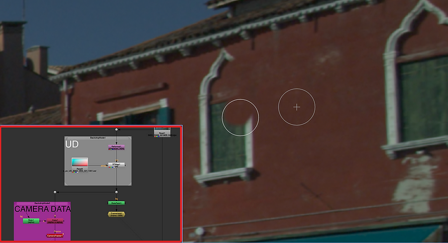
CameraTracker is designed to provide an integrated camera tracking or matchmoving tool, allowing you to create a virtual camera whose movement matches that of your original camera. Tracking camera movement in a 2D footage enables you to add virtual 3D objects to your 2D footage.

-
On this Scene, the water is moving so it would be tricky to track this area. I put the Copy and Roto nodes above the CameraTrackers node and mask out just above water and people walking on the side.
-
After mask out the area, change the mask option to 'Source Alpha' and set the range, and 'Track and Solve'
-
Create a single animated camera, a point cloud from the solved 3D points, and a Scene node by clicking the 'Create' on the Export
PLACE CARD ONT THE SCENE
-
On the PointCloud camera view, I selected the wipe mode and put two viewers.
-
On the Card node, I changed the Vertex Selection Mode and selected the vertexes, and created the a Card
APPLY AN IMAGE

-
I brought ScanlineRender node and connected to Camera and Card nodes.
APPLY A PATCH
-
To paint out one of the windows on the scene, I put the patch on and
ROTOPAINT
-
I connected FrameHold to the dot and set frame '1025' where it does not have blur. After that put the RotoPaint node and put the Clone tools around the one of the windows to paint out.


-
I drew Roto shape around the window and connected Copy node to FrameHold.
APPLY THE PATCH TO CARD
-
I selected the vertex around window from PointCloud viewer and placed the Card node by rotating and scaling down the size from the Top viewer.


WEEK 3 - 3D EQUALIZER
SETTING SHORTCUT

SET CAMERA AND LENS & FILMBACK

-
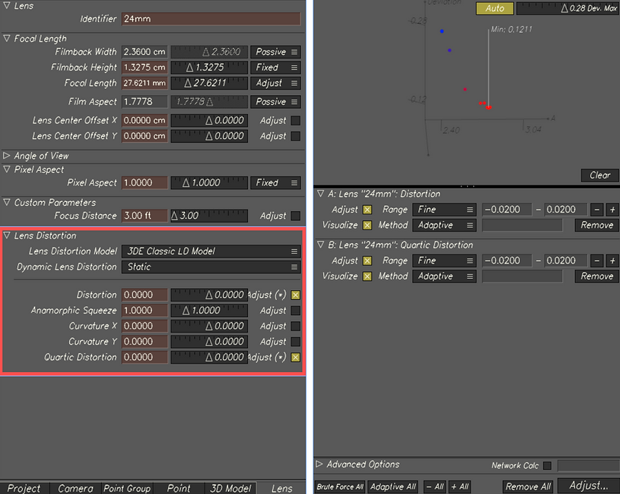
I set Camera and Lens setting. I changed Focal Length to '24mm' and Flimback Width to '2.36cm'. Because the scene is worked with square pixel, I changed the Pixel Aspect value to 1.
TRACKING THE SCENE
BASIC TRACKING

-
On the 'Manual Tracking Controls' mode, to create a new marker, zoom in on a marker position and 'Ctrl + LMB'.
-
To centre the marker, use the 'Gauge Marker' (Shortcut 'G') before track the marker.
TRACKING FROM THE MIDDLE OF TIMELINE

-
After centre the marker on the middle of timeline (Frame 70), then the marker will be tracked to forward. To track from the Frame 70 to backward the beginning, back to Frame 70 and press 'Flip Direction' (Shortcut 'R') and 'End Point' (Shortcut 'E') to change to Keyframe.
TRACKING OBJECTS LEAVING SCENE


-
With this marker, it is stopped in Frame 79 whilst Tracking. Go back a few frames before and make the marker fit the pattern to track the unique marker. After that, track the marker by one frame and press 'End Point' just before the marker goes out on the scene.
CAMERA SOLVE DIVIATION BROWSER

-
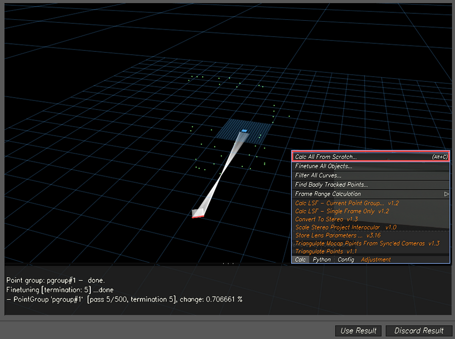
On the Calculation Points Panel, we can see all created markers on the scene.
-
After the points have been solved, you can see the quality of those points in the "Deviation Browser". The green line and number represent the average of all of the points, and the blue lines are all of the active points used for the calculation.
LINEUP CONTROLS AND 3D ORIENTATION


LENS PARAMETER & DISTORTION
FOCAL LENGTH OF LENS


-
To get exact 'Focal Length of Lens' information ('24mm' is not exact number), bring 'Parameter Adjustment Window' and recalculate.
-
After the adjustments and recalculating the solve, you can see the maximum value has reduced.


LENS DISTORTION
-
To change the lens distortion, change the Lens Distortion Mode to '3DE Classic LD Model' and tick 'Distortion' and 'Quartic Distortion'. After that, with the same process, Adjustment and recalculating.
WEEK 4 - LENSES AND CAMERA
SENSOR SIZE & FOCAL LENGTH

SETTING CAMERA CONSTRAINT


-
Camera Constraints tell how the camera is moving. 'Fixed Camera Position Constraint' makes the camera position not change over time.
CHANGE HEIGHT & CREATE DISTANCE CONSTRAINTS


-
After Adjustment and recalculating 'Focal Length, Distortion and Quartic Distortion, I put more accurate camera information into the scene based on Survey Data. The Survey Image tell the Camera Height is 1.7m so, I highlighted the camera and put the information.


-
To put more information into the Scene, I created Distance Constraints between two points from edges of the ledge
ADD LOCATORS AND GEO OBJECTS
ALIGHN SCENE


-
Before putting locators, I aligned 3 Points on the floor. I selected 3 points on the floor and clicked 'XZ Plane' on the 3D Orientation Mode. And I selected one of these points and made it 'Origin Point' on the scene.
ADD LOCATORS and GEO


-
To create locators on the scene, I grabbed all points and pressed 'Locators Create' on the 3D Orientation Mode. Through the 3D Models Panel, I created a Cylinder on the scene.
WEEK 5 - 3DE WORKFLOW AND NUKE
BAKE SCENE AND EXPORT ASSEST FOR NUKE


-
After the scene is baked, export project to Nuke (Cam Data)
[Location SHOTS/Door_freemove_01/2D/Data/MATCHMOVING/CAMERAS]


-
To export Locators Data, clicked the 'Export OBJ' on the 3D Orientation Mode.
SHOTS/Door_freemove_01/2D/Data/MATCHMOVING/GEO
-
To export Object (Cylinder) Data, clicked 'Export 3D Models as OBJ'.
SHOTS/Door_freemove_01/2D/Data/MATCHMOVING/GEO
-
After Exporting Locators and 3D Object Data, I exported Lens Distortion Data
SHOTS/Door_freemove_01/2D/Data/MATCHMOVING/UNDISTORT
BRING 3DE DATA TO NUKE

-
I drag and drop into Nuke Node Graph and Cataloged.
LENSE DISTORTION PIPELINE


-
This is general workflow of any cleanup distorted footage. Between 'UnDistortion' and 'ReDistortion' nodes, we do normally work.
CONNECT OBJ DATA ONTO SCENE

-
To connect geometry object onto the scene, I brought 'Scene node' and 'ScanlineRender' and connect the GEO nodes to the Scene node. I also connected 'Wireframe' and 'Constant' node to OBJ nodes to apply texture and colour on the objects.
CREATE PATCH


-
To create patch on the scene, first of all, I brought 'FrameHold' and 'RotoPaint', and I draw Clones on the sign on the wall. After that, I brought 'Project3D' and 'Card', and placed the Card on the where the sign was.
WEEK 6 - SET SURVEY & REF IMAGES

-
On this Survey Data, the image gives elementals measurements. So we were going to set points within these informations.

-
I created a point on the Scene and set this point as a origin point. On the Point Attribute Editor, I changed the Survey Type to 'Exactly Surveyed'.

-
I brought more new points and set the position for the floor.

ASSIGNMENT_01
3DE TRACKING

-
After I put Camera Information onto the scene, I tracked over 40points the scene.

-
After tracking the scene, I set Lens Distortion and Focal Length Adjustments to get low deviation.

-
I created distance constraints and aligned scene using Survey Data information.

-
I added locators and 3D Cube on the scene.
NUKE WORKFLOW
-
I exported Camera, Lens Distortion, Locator and 3D model data to Nuke.

CLEANUP
-
I Cleaned-Up patch on the fire exit sign with using RotoPaint


APPLY OBJ


FINAL

WEEK 8 - SET REF IMAGES
BRINGING IN REF IMAGES & NEW LENS


-
After importing 9 references images into the scene, I added another new lens and edited the lens' setting
SHARING TRACKS WITH REF IMAGES AND CAMERA

-
On the Manual Tracking mode, I created a point on the first ref image scene and switched to next ref image scene, and found where the point is on the first. I combined and shared the point together between the ref images.
-
I created 40 points on the scene.


WEEK 9 - LENS DISTORTION & GRIDS
CLASSIC LENS DISTORTION


-
After tracking the scene and setting the Lens Setting (Changing the Camera Constraint to Fixed), I changed the value of Lens Distortion and Quartic Distortion to make the red dot close to green X box on the Lineup mode.
USING A GRIDS TO LENS DISTORTION

-
After I changed the Lens Distortion Model to '3DE Radial', I brought new reference camera and Grids Footage on the 'Distortion Grid Mode'.


-
I dragged the red Grid to a corner of the Checkerboard and clicked 'Snap'.


-
To expand the Red Grids, I added points.

WEEK 10 - WORKFLOW NUKE TO MAYA
-
I brought the Baked Scene into 3DE and exported this as Maya file.
-
Before I import the exported Maya Scene, I made Image Sequences which is applied LensDistortion through Nuke.
-
I put these image Sequences into the ImagePlane


-
Before I put Object on the Scene, I scaled up the Size of ImagePlane and Camera Film Back value to match the locators with the scene.


-
I imported Sphere and Plane meshes and Light on the Scene, and assigned Arnold Material on the meshes.
-
I set a camera setting to render image sequences and brought to Nuke.


NUKE WORKFLOW

-
After Bringing into Nuke, I cleaned up the Patches on the Floor.
ASSIGNMENT_02
MY FOOTAGE

Green screen set
REFERENCES


WORKFLOW
TRACKING THE SCENE (3DE4)

ADDING ANIMATION (MAYA)
-
After tracking the scene in 3DE, I brought the skeleton model into the Maya and added 'Fluid' Animation.


Anolrd Render
NUKE

OCCULATION

shadow matte

diffuse

volume

RGBA

NORMAL


FINAL
...